
Just to remind, the set consists of:
- Piko 40200 Talent 2 model (reviewed here)
- Piko 46211 DCC decoder
- Piko 46190 sound module
I start off by identifying the car that needs the modification. I'm working with one car only so separating it from the rest and securing the remaining units somewhere safe is a good idea.

Now I need to open the car. The manual says "pull the body out and lift upwards".

It's easy if you know where the latches are (there are always some latches, right?). But if you don't, you have to locate them gently. My method involves using toothpicks. I discovered they're made of a very soft wood and they do not damage plastic parts or paint.

It's open now, no damage was done but... I still don't know where the latches were ;)

Let's take a look at the Piko 46211 decoder now. This part is really tiny. It's shown here next to a metering tape (the unit is centimetres) and the soldering iron tip (one I bought especially for this occasion). The decoder features four copper pads that I will solder the sound module to.

The Piko 46190 sound module is slightly larger but it does not really matter. There's no soldering to do on this part. The speaker does need soldering but that step is far from difficult.

The connection is colour coded so there's no doubt about how to route the sound module wires to the decoder.

Yeah! I was successful. The four wires are soldered now and it does not look bad. The red wire could have a better connection but honestly - this imperfection was not visible at all, until I later opened and analysed the photo on my computer.

This is the first moment when I can test the sound. And it works right away. From now on I'm re-testing it after every single change I make.

Now I need to fit everything inside the locomotive's body. The trickiest part is the speaker which goes way to the bottom. The manual does explain how to do it though.

Unfortunately this requires disconnecting some of the factory soldered wires. So I'm taking this photo to know how to reconnect them later.

It's enough to unsolder the cables at the front of the car and on the sides. The back cables can stay - we do not need to remove the PCB completely, we can just move it aside.

Once the PCB is no longer in the way, the blue "interior fitting" part can be removed. This involves unscrewing four screws: two on the top and two on the bottom. The speaker hole is blocked by a metal part that needs to be removed, too. That's another two screws.

Now I can finally install the speaker. The question is: where do I put the wires? Piko's intention was probably to allow the usage of the two grooves leading to the engine part but the provided wires are too short for that.

My answer to that is in replacing the wires with my own. But my cables are too thick. It won't work.

So let's try another type of wire. This one is recycled from old headphones. It's very thin and very flexible.
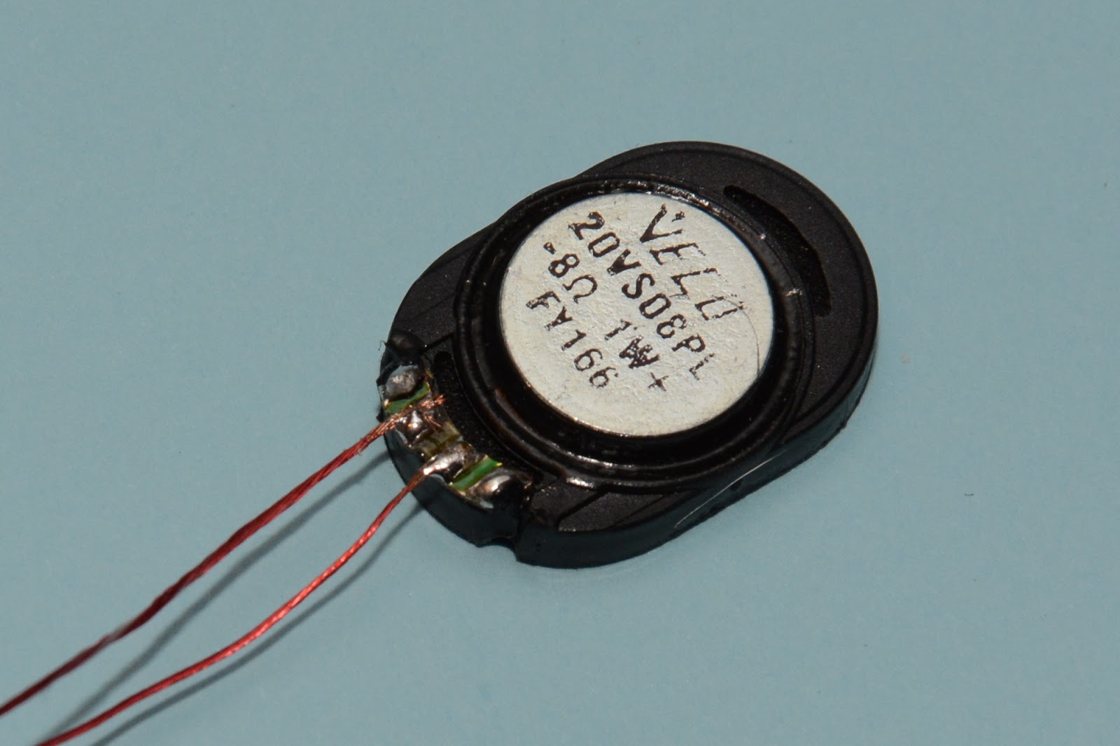
Seems it fits. Time to test again. And yes, it works.

Let's shorten the wires and start re-soldering the original cabling.
The photo below clearly proves that I forgot to reattach one of the screws. Something I realized only after I closed the model completely...

Here the complete model is back. Everything fits in and the sound still works!

The locomotive does not offer a dedicated space for the sound module. And it has to be placed "somewhere". Piko provides double sided sticky tape pieces to allow attachment anywhere in the model. But really - it's not like we have much choice here. And the available space is so small that there's no way the sound module PCB will move at all. So I'm just using some insulation tape to protect the circuits from shorting and nothing more. Of course the module will occupy part of the passenger area of the train.

It's time to close the unit. This is surprisingly easy but not perfect. There's a very, very tiny gap left. It's definitely not visible unless you're actively looking for it. And it just might be that I could have done a better job here.
The wires are unfortunately visible through the windows. One might consider making those windows black / non-transparent to hide the electronics.

This is what the decoder looks like now when peeking through the hole in the roof. Obviously it cannot be taken out, as it is soldered to the sound module. The blue insulation tape is used to hold the speaker cables in place.

That's it! The installation is done.
The documentation fails to describe all the available DCC functions provided by the 46211/46190 combo. So here they are (identified by "trying") for your convenience:
- F0 - Headlight
- F1 - Engine Sound / Interior Lighting
- F2 - Long Horn (sound)
- F3 - Shunting Speed (Half Speed)
- F4 - Acceleration/Deceleration
- F5 - Modulated Horn (sound)
- F6 - Door Closing Warning (sound)
- F8 - Mute
- F9 - Short Whistle (sound)
- F11 - Cooling Exhaust (sound)
- F13 - "Abfahren" (sound/talk)
- F16 - Long Whistle (sound)
- F17 - Coupler (sound)
And here's a demo movie proving that it really works :)
I do have two more notes about the sound I'm getting after the installation.
- The audio effects sound a little "metallic" to me. Perhaps it's meant to be this way and it definitely fits this modern model. But it might be surprising at first, too.
- The audio does seem loud enough but it does not hide the noise of the model completely. I can still hear either the model's engine or the wheel-rail friction sound in the background.
Summary
The soldering was not as difficult as I thought it would be. Using flux and a small soldering tip, I had really no problem connecting those four tiny pads. Fitting it all in was not easy and required some creativity. The provided manuals are good and help very much even though they do not answer all the questions. If there were any improvements I might suggest for the future, I'd say:- Piko, please allocate some space for the sound module inside the model. Looking at the locomotive's body, a second roof compartment seems possible.
- Piko, please do not make us unsolder / resolder the model. In case the PCB needs to be removed during upgrade, please introduce sockets and plugs instead of soldered connections.
THANK YOU For this guide, I was handed this job to do without the instructions and I would have never gotten it otherwise.
ReplyDelete