I have previously found a way to measure the DCC track voltage using a home made meter. This method has worked for me for some time now - it's reliable and very easy to use. But how about something more extravagant? How about using a real oscilloscope for that?
Oscilloscopes are rather expensive devices and are not really portable. And if they are portable, they tend to be even more expensive. I can't afford spending this kind of money on something that is not crucial for my hobby. Luckily there's a cheaper option.
DSO138 is a DIY oscilloscope kit from JYE Tech. It is easily obtainable on Ebay with prices going below $20 including shipping. I've ordered one from China and it arrived quickly and in good shape. I wasn't expecting a nice box at this price point and I did not get one:
The kit comes in a plastic bag. It contains everything you need to build your own budget oscilloscope. There's a PCB, lots of elements and a probe. It even features a colour LCD screen. Considering the price, it looks really nice.
The set includes a build manual. Its quality is a huge surprise to me. It's several pages long, it's written in a proper English and it really covers the installation very, very well. It's difficult to make a mistake here, and if you do - troubleshooting steps are provided, too!
Soldering the kit took me around 3 hours. Some SMD elements were rather tricky and I failed to install the USB port properly. But other than that - it was an interesting soldering exercise.
Alright, let's test this thing. The device offers a 1kHz 3.3V test signal that can be used during bring-up and troubleshooting. As soon as that worked, I connected the probe to my 16V transformer. Here's the image I got:
Looks like a proper AC signal to me. The peak voltage seems to exceed 20V which is expected for a 16V sinusoid. Unfortunately this test already shows the biggest limitation of the device. While it is supposed to handle up to 50V peak voltage, the screen and the controls don't allow to see such signal in full. The oscilloscope is limited to a maximum of 5V per division which results in just a 40V peak-to-peak display.
OK, let's finally see some DCC signal. Here's the output of the Fleischmann/Roco system I use for my N-scale trains. I placed the device next to my home made DCC voltage meter and compared the results.
It's definitely a digital signal I was expecting. The peak voltage seems to be just below 15V. My meter shows 13.5V but I have to remember to add around 1.3V due to the bridge rectifier in the meter. So it matches: 13.5V + 1.3V is almost 15V!
Let's try another system. Now I'm using the output of Uhlenbrock Power 8 booster intended for my G-scale trains.
My voltmeter indicates 24.8V (23.5V + 1.3V) and the DSO138 device... went out of range again. The voltage is more than 40V peak-to-peak and cannot be shown correctly. What a pity. I think I need a different probe...
Update
Very soon after I had posted this article, I've learnt of a hidden functionality in the DSO138 firmware. This undocumented feature is triggered by holding the OK button for 3 seconds and it allows the user to display a summary information for the signal under analysis. It looks as follows:
The interesting part here is that the measured voltage values seem to be correct even despite the signal being out of range for the display to show. So perhaps an extra probe is not needed at all...
Summary
So what is DSO138 and is it useful? It's first of all a soldering exercise that makes you feel good once it turns out to be working. Is it useful? Well, it does allow me to measure the DCC voltage. Of course the precision is probably not there but... it's not really needed for my use. The biggest caveat is the limited sensitivity control which makes the device less useful for large scale unless a different probe is used. Would I recommend buying it? Yes, but just for the fun of soldering!
I've had the desire to own a test rolling road ever since I started this blog. Such accessory is not only useful when working with your trains but also when shooting videos for YouTube. And here it is - now I have one.
I've decided to go for a solution from a company I've never heard about. They're called Brahmer Modellbau and I think they sell exclusively on Ebay. The package I ordered arrived very quickly without any special packaging - just in a sturdy cardboard box.
The interesting fact here is that every element of the rolling road can be purchased separately. That's the main reason why I considered this offer interesting. For a start I've decided to buy just enough for my current PIKO BR80 locomotive with an option to extend the set in the future. And so I picked these three parts.
The most important element is the rolling block itself. I've bought two of those. They look pretty solid. The fact that rollers seem to be attached to the base with just some screws is a little worrying but the element gives a very reassuring feeling when held in hand.
The other part is a support block. Those are available in two sizes - a short one and a long one. For now my setup requires just a short block to allow contact for the locomotive's power pick ups. This part is also built with screws but it looks pretty good to me.
And here's what the set looks like when placed on the track. It fits nicely and is very stable. Nothing really to complain about.
Alright. Let's see it in action:
It seems to work just fine. Two facts however can be seen in the movie:
The locomotive is quite shaky at full speed. I don't see any risk here however. The entire setup seems stable and safe.
Not all the rollers take part in action. I must have not placed the locomotive perfectly and it presses harder against some elements than against the others. This seems fine though.
Conclusion
The rolling road from a little known company looks perfectly fine to me. I will be buying more elements in the future to make my set more universal. I might even go for an N-scale version, since that is also offered in their catalogue. Price aside (as it's not cheap) can't find any reason not to recommend the product!
Unlike in Westeros, in Poland the spring is coming. So it's time to make some serious preparations for the new G-Scale season. I've decided to finally try electric control of my - not yet installed - Piko turnouts.
The elements I will be connecting together are:
Piko 35221 turnout
Piko 35271 electric switch
Piko 35266 lantern
Here's the set:
Let's start with the electric switch. It comes in a bag that contains the switch itself, two screws and a one page manual.
The lantern package is similar. We get the lantern, one screw, a manual and an extra lantern cap for opposite direction turnout.
The manual suggests to remove the spring from the turnout. And that's what I'm doing. It's a very easy operation. Actually as soon as the cap is out, the spring may jump out by itself. That's what happened in my case.
Update:
My further tests show that removing the spring is not necessarily required. My switch seems to work fine with this element still installed. And keeping the spring makes the turnout more stable in terms of keeping the point rails in place.
A little bit of planning now. I guess this is how it will go. Lantern on the left, the electric switch in the middle and then the turnout on the right.
First the lantern. It needs to be opened and then we're supposed to push it into the switch until it "clicks". Easy. One screw holds the two items together.
When closing the lantern, we're expected to pay attention to the position of a spring element. That's what the manual says. But my unit does not have any spring. So it's either missing or the manual is not up-to-date. I'm continuing without the spring.
Time to connect the wires. This requires opening the electric switch in two places. One is the entrance for the cabling, the other exposes the screws of an electric terminal.
The wires are connected now. The small element in the middle is made of rubber. I guess this is what makes the entire system water-proof. It's definitely sitting tight on the cables.
This is the moment I've realized I actually wanted the switch to be placed on the other side of the turnout. So I disassemble everything and connect again. Two screws hold the switch and the turnout together.
The lantern needs a separate power source. I guess I will just connect it to the track on my layout. For testing purposes however, I'm using an extra DC power supply.
It works right away. This is what the complete set looks like in a well lit environment:
And here in a slightly darker setting:
I've also made a short movie showing the switching process:
All in all a very painless installation. Maybe except for the missing spring. I still wonder whether it should be there or not. I guess I'll know when I buy another lantern...
I have received the set shown below around two months ago. Once I saw how small the elements were I got scared and decided to postpone the installation. But finally I've gathered enough courage and performed all the needed steps. I'm very proud today to share the results with everyone.
And the goal of the installation is to upgrade the beautiful EMU from PIKO with digital control and sound functions.
I start off by identifying the car that needs the modification. I'm working with one car only so separating it from the rest and securing the remaining units somewhere safe is a good idea.
Now I need to open the car. The manual says "pull the body out and lift upwards".
It's easy if you know where the latches are (there are always some latches, right?). But if you don't, you have to locate them gently. My method involves using toothpicks. I discovered they're made of a very soft wood and they do not damage plastic parts or paint.
It's open now, no damage was done but... I still don't know where the latches were ;)
Let's take a look at the Piko 46211 decoder now. This part is really tiny. It's shown here next to a metering tape (the unit is centimetres) and the soldering iron tip (one I bought especially for this occasion). The decoder features four copper pads that I will solder the sound module to.
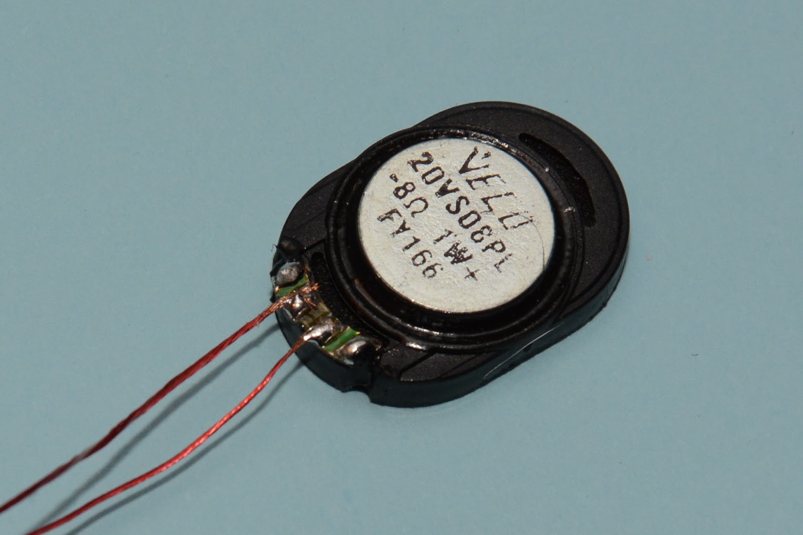
The Piko 46190 sound module is slightly larger but it does not really matter. There's no soldering to do on this part. The speaker does need soldering but that step is far from difficult.
The connection is colour coded so there's no doubt about how to route the sound module wires to the decoder.
Yeah! I was successful. The four wires are soldered now and it does not look bad. The red wire could have a better connection but honestly - this imperfection was not visible at all, until I later opened and analysed the photo on my computer.
This is the first moment when I can test the sound. And it works right away. From now on I'm re-testing it after every single change I make.
Now I need to fit everything inside the locomotive's body. The trickiest part is the speaker which goes way to the bottom. The manual does explain how to do it though.
Unfortunately this requires disconnecting some of the factory soldered wires. So I'm taking this photo to know how to reconnect them later.
It's enough to unsolder the cables at the front of the car and on the sides. The back cables can stay - we do not need to remove the PCB completely, we can just move it aside.
Once the PCB is no longer in the way, the blue "interior fitting" part can be removed. This involves unscrewing four screws: two on the top and two on the bottom. The speaker hole is blocked by a metal part that needs to be removed, too. That's another two screws.
Now I can finally install the speaker. The question is: where do I put the wires? Piko's intention was probably to allow the usage of the two grooves leading to the engine part but the provided wires are too short for that.
My answer to that is in replacing the wires with my own. But my cables are too thick. It won't work.
So let's try another type of wire. This one is recycled from old headphones. It's very thin and very flexible.
Seems it fits. Time to test again. And yes, it works.
Let's shorten the wires and start re-soldering the original cabling.
The photo below clearly proves that I forgot to reattach one of the screws. Something I realized only after I closed the model completely...
Here the complete model is back. Everything fits in and the sound still works!
The locomotive does not offer a dedicated space for the sound module. And it has to be placed "somewhere". Piko provides double sided sticky tape pieces to allow attachment anywhere in the model. But really - it's not like we have much choice here. And the available space is so small that there's no way the sound module PCB will move at all. So I'm just using some insulation tape to protect the circuits from shorting and nothing more. Of course the module will occupy part of the passenger area of the train.
It's time to close the unit. This is surprisingly easy but not perfect. There's a very, very tiny gap left. It's definitely not visible unless you're actively looking for it. And it just might be that I could have done a better job here.
The wires are unfortunately visible through the windows. One might consider making those windows black / non-transparent to hide the electronics.
This is what the decoder looks like now when peeking through the hole in the roof. Obviously it cannot be taken out, as it is soldered to the sound module. The blue insulation tape is used to hold the speaker cables in place.
That's it! The installation is done.
The documentation fails to describe all the available DCC functions provided by the 46211/46190 combo. So here they are (identified by "trying") for your convenience:
F0 - Headlight
F1 - Engine Sound / Interior Lighting
F2 - Long Horn (sound)
F3 - Shunting Speed (Half Speed)
F4 - Acceleration/Deceleration
F5 - Modulated Horn (sound)
F6 - Door Closing Warning (sound)
F8 - Mute
F9 - Short Whistle (sound)
F11 - Cooling Exhaust (sound)
F13 - "Abfahren" (sound/talk)
F16 - Long Whistle (sound)
F17 - Coupler (sound)
And here's a demo movie proving that it really works :)
I do have two more notes about the sound I'm getting after the installation.
The audio effects sound a little "metallic" to me. Perhaps it's meant to be this way and it definitely fits this modern model. But it might be surprising at first, too.
The audio does seem loud enough but it does not hide the noise of the model completely. I can still hear either the model's engine or the wheel-rail friction sound in the background.
Summary
The soldering was not as difficult as I thought it would be. Using flux and a small soldering tip, I had really no problem connecting those four tiny pads. Fitting it all in was not easy and required some creativity. The provided manuals are good and help very much even though they do not answer all the questions. If there were any improvements I might suggest for the future, I'd say:
Piko, please allocate some space for the sound module inside the model. Looking at the locomotive's body, a second roof compartment seems possible.
Piko, please do not make us unsolder / resolder the model. In case the PCB needs to be removed during upgrade, please introduce sockets and plugs instead of soldered connections.