The next batch of my garden track arrived some time ago but the poor weather discouraged me from doing any work outside. Luckily it got better last Sunday and I was able to start. The first step was again attaching the new track to mark the path where to bed should be.
After that it was digging the ditch and filling it with grit. The same as previously.
The track was not very flat after it was placed on the bed. And that was not surprising at all. It can be even seen in the magnification of the above photo:
I was not terribly worried about this for two reasons:
I got some feedback from more experienced colleagues at the MyLargeScale forum
I took the following photo of a real life track that is in daily operation and it's not really straight at all
Bad, isn't it? One could wonder whether that track is safe.
I fixed some of the obvious problems with the track geometry by adding or removing stones. It looked pretty straight after that.
My next step was fixing the track in place but before that I had to perform a test:
"Fixing in place" was going to be achieved by mixing some finer granularity grit with cement and using it to fill the space between the sleepers:
That is too much cement in the mix, you definitely need less
I filled the gaps and distributed the ballast evenly with a brush:
Now all I needed was a willing little helper. Kids usually love playing with water. And my daughter is no exception here. She was very happy to turn the dry cement into a glue that would hold the ballast together.
72 hours later the track is fixed in place. It's actually so solid that I wonder whether making any changes will be as easy as I hoped it would be. And this is what it looks like:
Yes, it's dirty... And I thought I cleaned it well when watering the cement.
Some lessons learnt:
Use less cement in the mix
A finer granularity ballast would be so much better and easier to use
There's some serious track cleaning ahead of me which could have been avoided (at least to some extent) by spraying the water more carefully
My newly extended track is now several meters longer and next weekend I'm going to run my train on it!
I've been trying to put interior lighting into my N-scale passenger cars for some time now. Of course I could have used kits prepared by the well known companies but I did not like that idea that much due to the reasons described here. That's how my chase after a perfect and universal lighting kit started.
The N-scale is difficult when it comes to putting anything inside the cars. The available space is extremely small, so I had to be very picky about the components I would use. The LED strips are very cheap and around 9mm in width so they seemed like a perfect choice for a start. But I knew of course, that I would need to fit more in there.
My very first attempt was also a very simple one. I used a piece of a LED strip 3 segments long (~15cm and length) and connected a resistor in series. Installation was very easy thanks to the adhesive back of the strip. This is what it looked like:
Just the LED strip and a 4.7kOhm resistor
And it worked of course as can be seen in this video from over a year ago:
But of course the solution was too simple to be good. It had two major flaws:
the light in the car was active in one direction of travel only due to the LEDs requiring a correct polarity
the light was flickering when the track was not 100% clean
So I've made another attempt and created a circuit that was supposed to work better. Two rectifiers were added (two not one - to minimize internal wiring) along with some capacitors. The components were SMD type and they were sufficiently small. Here is what it looked like:
2x100uF capacitors
Please notice the rectifiers at both ends of the LED strip. They're soldered at 90 degrees so that they fit into the car's shape. This is N-scale after all and any space is hardly available. Attaching them exactly at the required angle was pretty difficult.
The result was better than in the first attempt. The light was active no matter what the polarity was. And that was important to me since I was doing DCC operation at that point already. And the LEDs were blinking much less thanks to the capacitors. If only the soldering was easier...
That was also the moment when I started experimenting more seriously with different versions of electrical circuits. I discovered that my current solution was not an optimal one due to wrong placements of the capacitors. They should have had an additional resistor before the LEDs to increase the discharge time. Just as described here.
That circuit would have been extremely difficult to solder on a LED strip. And that's why I decided to try using a PCB board as a base instead of the strip. I knew nothing about PCBs so I just bought a universal one and started building the electrical circuit. The result probably violated dr. Frankestein's intellectual property rights.
One 100uF capacitor in this circuit gives a better result than two in the previous one
It was extremely difficult to solder. It took me an entire day just to make that one piece. But did it work well? Oh yes, it worked exactly as I wanted my lighting solution to work. Flawless operation in both directions and hardly any noticeable blinking.
But that soldering effort was unacceptable. I had to come up with something better. And at that moment one of my colleagues suggested that I should design my own PCB.
This was again a topic I knew very little about. But it turned out not to be that difficult at all. In less than two evenings I had my design ready and was looking up for ways to build it.
The PCB is designed in a way that allows cutting it to any needed length
To my surprise, PCB making is actually cheap. I've found an engineer who would do it for less than 2 Euro per piece. The boards arrived two weeks later.
They did not look that great but they did not have any real flaws, either. So as soon as I had the time, I've decided to build one lighting solution.
To my surprise (again!) soldering elements to this kind of board was extremely easy. I've built the complete circuit in around one hour. And what's also easy to notice, it looked quite nice even despite my rather poor soldering skills.
A flexible wire is needed for wheel pickups connection. Here I'm using a wire extracted from some old headphones.
And of course it worked great, as expected... I'm going to equip all my coaches with this kind of lighting.
***
It took me over a year of thinking, gathering knowledge and experimenting before I actually came up with something that I'm happy with. And I can now create a lighting kit in less than one hour with a total cost of around 3 Euro. Pretty good, I think, for somebody who started from scratch.
Here's a video showing comparison of two cars of the same type - one equipped with my initial kit, and one equipped with the latest one. Or in other words: blinking vs no blinking:
Layout builders usually try to create something that looks realistic. And by "realistic" they don't mean just fitting in the terms of scale or common sense. They also try to present a specific place and/or a time period in the most accurate way.
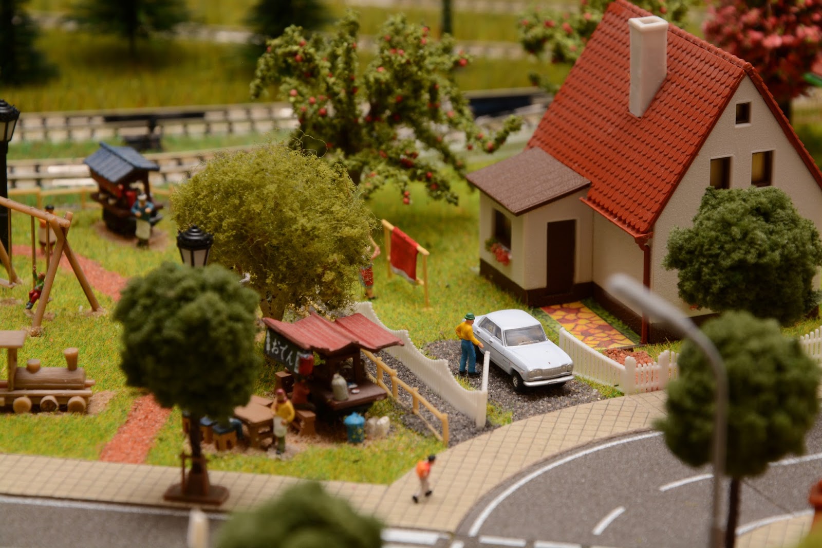
Well, that's not me... I just like things to be pretty and detailed. That's why I don't mind a Japanese bus parked next to a Polish house or an American train being dispatched by a station worker in a German uniform. As long as it is pleasing to my eyes, I like it.
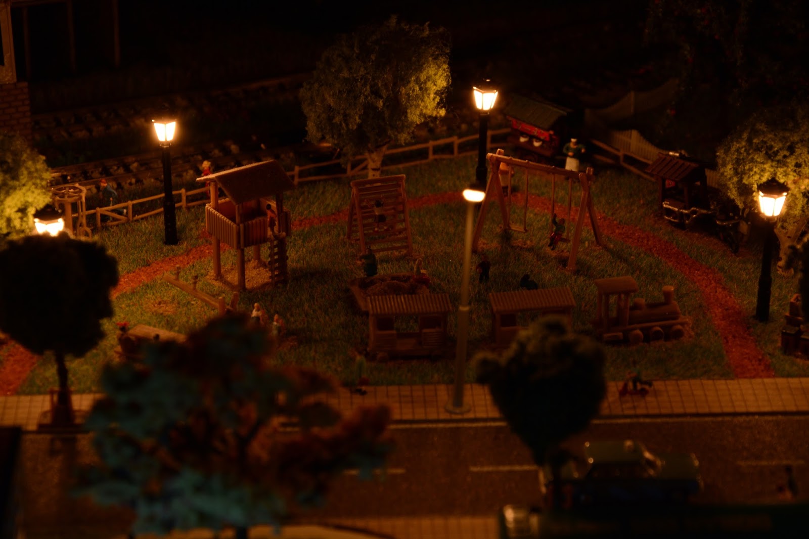
The outcome of this philosophy is my tiny N-scale layout which I named Korfantów. The layout is really small at around 90cm x 50cm. At this size it's obviously densely packed and is not really realistic at all. But do I consider it pretty and does it make me feel better when looking at it? Definitely yes.
Here are some photos of the Korfantów layout. Each one is taken in two versions to show the day and night views. Enjoy!
Another weekend with some very nice weather gave the opportunity to make more progress on my garden train. I've already managed to fill the gaps in the ballast with some extra stones, and the next step was to lay the track. Here's what it looked like at first:
I was surprised by how nice it was right at the start. Of course some of the track was flying in the air due to an uneven distribution of the ballast...
...and I spent some significant time trying to correct that by adding or removing grit from the bed. But once I got it to a satisfactory level the track was pretty stable and looked even better.
Of course it's not all roses. The track is still not perfectly flat and the longest straight section is not really that straight as can be seen in this photo:
I'm not sure what to do about this. I'm not even sure whether I should worry about this at all. I think I'll take another look at the issue once I have some more track.
And yes, more track is exactly what my layout needs now...
Here's a video showing my train going around this very, very small loop: