But it's of course not just a building but a lighthouse. It needs a beacon light. So the emitted light should be either spinning or blinking. Creating a rotating light source seemed complicated so I decided to go for one that would just switch on and off. This can be of course achieved by using a multi-vibrator circuit.
The basic one can be seen below. There's not much to be said about it. The frequency of blinking can be adjusted by using different values for resistors and capacitors. And I really think we have a full freedom of choice here. One thing I would be careful about is making sure that R1 and R2 resistors are always of higher values than R3 and R4.
But the basic circuit was not good enough for me. Most notably - I wanted a blinking light, but one with a nice fade in and fade out effects. Therefore I had to make some changes:
My circuit differs from the basic one in three areas:
- I removed one of the LEDs as I needed only one blinking light
- I've added a bridge rectifier at the input - the circuit needs a proper polarization and I just didn't want to worry about that when connecting the power supply
- For the nice fade in and fade out effects I added an extra capacitor parallel to the LED
- R1 = R2 = 9.4 kΩ
- R3 = 860 Ω
- R4 = 110 Ω
- C1 = C2 = 470 uF
- C3 = 2200 uF
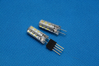
They're LEDs so they don't take much power. They're cheap - $0.50 a piece. They're powered with 12V, so they're safe. And their connector (which is G4) fits pretty nicely into a standard PCB socket. So I ordered them...
Here's my first prototype for the beacon light. It took some experimenting to decide the right values for the elements, and this way of building the circuit was great for the first step. And it also allowed me to easily monitor the voltage on the light bulb. Now I know that I need to provide at least 16V at the input in order to have around 12V on the LEDs.
Once I was happy with the light output, I had to solder the circuit. As always - my creation does not look good but works as expected!
I had two more goals to achieve:
- I wanted to protect the circuitry from the bad weather. I didn't think it needed to be perfectly sealed, but some level of protection was desired.
- I wanted to make the light more diffused. The light the LED bulb was producing was "too direct" for me.
Here's my circuit installed inside the plastic box. My favourite hot glue proved to be useful, as always :)
More hot glue and the whole beacon light bulb is now attached to the base of the lighthouse. I'm starting to be proud of my creation at this step!
The lighthouse is closed. The light is lit. Looks good to me!
And it looks even better when moved outside. The photo was taken just before dusk. The light is not very strong but it was not meant to be - I do not want to disturb my neighbours' sleep.
I've also shot some short videos at different phases of my work. They show the frequency of the blinking as well as the fade in/out effect. Enjoy!


Nice job. Do you have drawn up plans to build the lighthouse? If so, please post it.Tim
ReplyDeleteHi, My father in law wanted a lighthouse like that fades. Since I have a degree in electronics he asked me to make something for him. Here is one that uses incandescent light that has a little smoother fade in/fade out. https://www.youtube.com/watch?v=750ElBA4Rzo I did this by programming a microprocessor. This also has a "morse" mode that when turned on blinks out "happy fathers day"
ReplyDeleteHi Tim, I hope you do pot the plans because I love your lighthouse and would like to have a go at making one. Thankyou for putting this on.
ReplyDeleteSorry Tim I put your name by accident. Never mind
Delete